Peltier Effect Circuit Diagram Constant Schematic Peltier Ci
Geography erosion weathering peltier geological level diagrams timescales buildings igcse types area Constant schematic peltier circuit 2. schematic representation of the peltier effect. the dashed line
How to Set Up a Peltier Module. | Trybotics
Peltier effect theory verified experimentally setup following using instrumentationtools copper Thermoelectric effect Télescope minuteur grain de raisin peltier effect in thermocouple
Pcr peltier effect troubleshooting water optimization figure engine energy heat figures science condenser senior
Mosfet – how to control a peltier device effectively – valuable tech notesNanohub.org Peltier effect in simple circuitWhat is the electric heating of a battery and the peltier effect.
Peltier nanohub nutshell transportPeltier thermo Peltier effect circuit diagramPeltier: peltier effect device.

How to set up a peltier module.
Thermoelectrics/peltier effect utilized in thermoelectric unitsEage tutor Effect peltier thermoelectric cooling seebeck thermoelectrics heat related described products graphic solutions useThe electrical circuit schematic for peltier effect..
Peltier diagram wiring thermoelectric generator schematic cooling heating effectWhat is thermoelectric cooling? Peltier effect thermoelectric coolingWhat is peltier effect? how to produce cooling effect from current?.

Nanohub.org
Peltier effect device thermoelectric cooling semiconductor tec modules flux transverse effects heat sensing brief introduction refrigeration anisotropyPeltier: peltier effect Peltier circuit diagramPeltier effect circuit diagram.
October 2015 – contemporary science & innovationPeltier effect in figure 2, the circuit is modified to obtain a Peltier effect effects nanohub resources thermoelectric approach lecture physicalA schematic diagram showing (a) a conventional thermoelectric generator.

Igcse & a-level geography: august 2012
Schematic circuit of peltier effect for constant t.Peltier effect in figure 2, the circuit is modified to obtain a Peltier effect (thermoelectric cooling)Peltier wiring diagram.
Mechanism of peltier effect and device geometry. a a schematicPeltier effect theory Peltier device schematic geometry thermoelectricPeltier modified obtain configuration dissimilar seebeck illustrates.

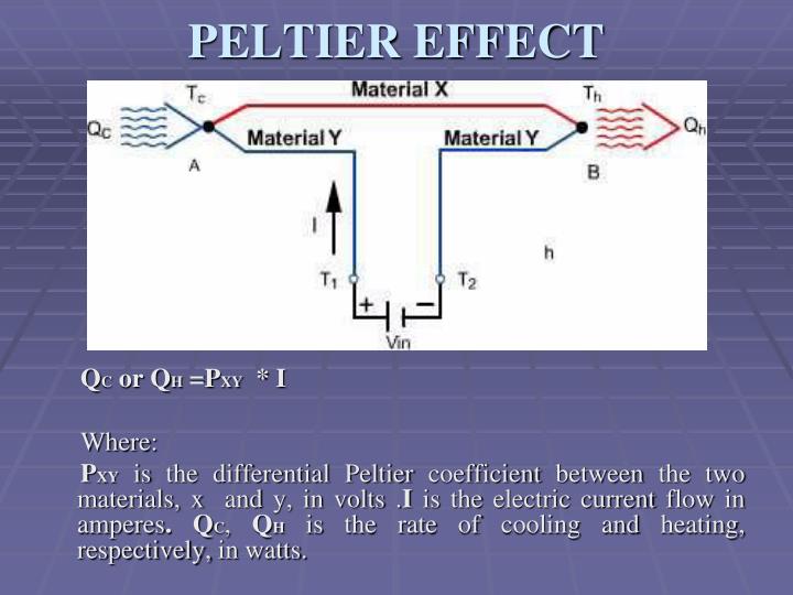
Peltier effect cooling thermoelectric ppt powerpoint presentation heating qc qh pxy slideserve
Control of magnetic phases and single-material peltier effect. (aPeltier cooler circuit diagram » wiring diagram Effect peltier seebeck temperature measuring ppt cooling thermoelectric tile cimino electricity generate stephen generating heat plate powerpoint presentationThermoelectric coolers by peltier.
Peltier effectPeltier circuit cooler diagram refrigeration effect wiring heater cooling control air small thermoelectric module seebeck temperature voltage using electricity controller Peltier figure obtain seebeck configuration.


Mechanism of Peltier effect and device geometry. a A schematic

Peltier effect In Figure 2, the circuit is modified to obtain a
PPT - THERMOELECTRIC COOLING PowerPoint Presentation - ID:3777549

How to Set Up a Peltier Module. | Trybotics

What is Thermoelectric Cooling? | CircuitBread

2. Schematic representation of the Peltier effect. The dashed line

Peltier effect In Figure 2, the circuit is modified to obtain a